
What You'll Build
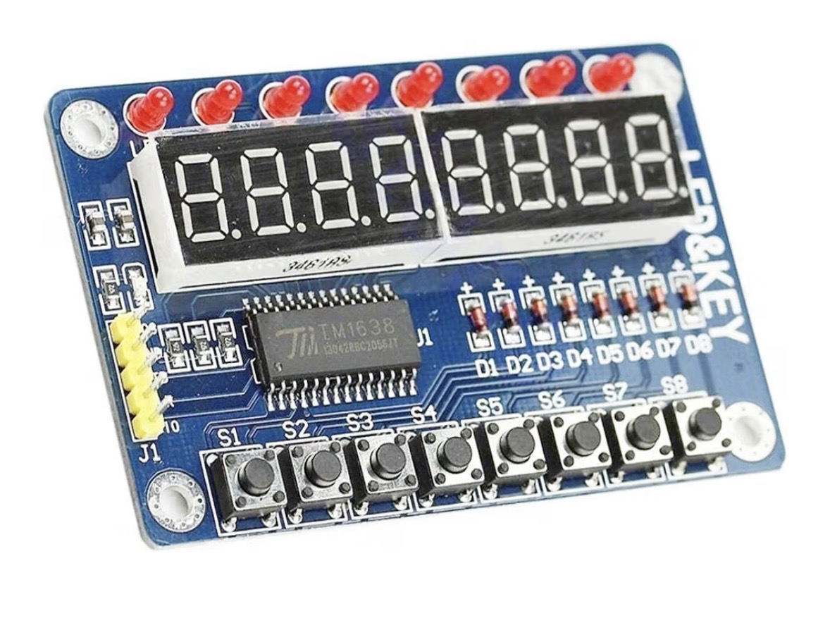
A real LED output controlled by the ESP32-S3 through DALE. The LED is already part of the TM1638 module, so your first experiment can focus on the idea of an output instead of building a separate circuit.
What You'll Need
- DALE with ESP32-S3
- TM1638 module
- Jumper wires for the module connection
What You'll Learn
- What an output is.
- How software can control real hardware.
- How DALE addresses an individual TM1638 LED.
- How a Boolean TRUE/FALSE state can control an output.
- How visual logic becomes real Arduino code.
Connect It
Connect the TM1638 module to DALE using the module configuration shown in DALE. If you have already configured the TM1638 in DALE, use those same connections.
Try It in DALE
1. Open DALE
Connect to DALE normally and open dale.local in your browser.
2. Open the TM1638 Lab
Verify that the TM1638 module is connected and responding.
3. Turn on one LED
Choose one of the TM1638 LEDs and switch it ON.
4. Turn it off
Switch the same LED OFF.
What Just Happened?
An output is something the controller changes in the outside world. In this case, the ESP32-S3 communicates with the TM1638 and tells it whether a particular LED should be on or off. DALE lets you see that behavior first, before asking you to program it.
Build It in Logic Builder
Now recreate the behavior visually. Add a Virtual Button and a TM1638 LED (TM LED) block. Select the same TM1638 LED you just tested, then connect the Virtual Button's Boolean output to the TM1638 LED block input.
Run the logic. Virtual Button ON → TM1638 LED ON. Virtual Button OFF → TM1638 LED OFF.
BUILD IT VISUALLY. SEE THE REAL CODE.
Show Me The Code
Open Show Me The Code for your Logic Builder project. Find the readable variables for your Virtual Button and TM1638 LED, then look at how the generated sketch initializes the TM1638 and changes the selected LED state.
DALE's generated sketch can be copied into the Arduino IDE and burned as a standalone project when you're ready to work directly with Arduino.