
What You'll Build
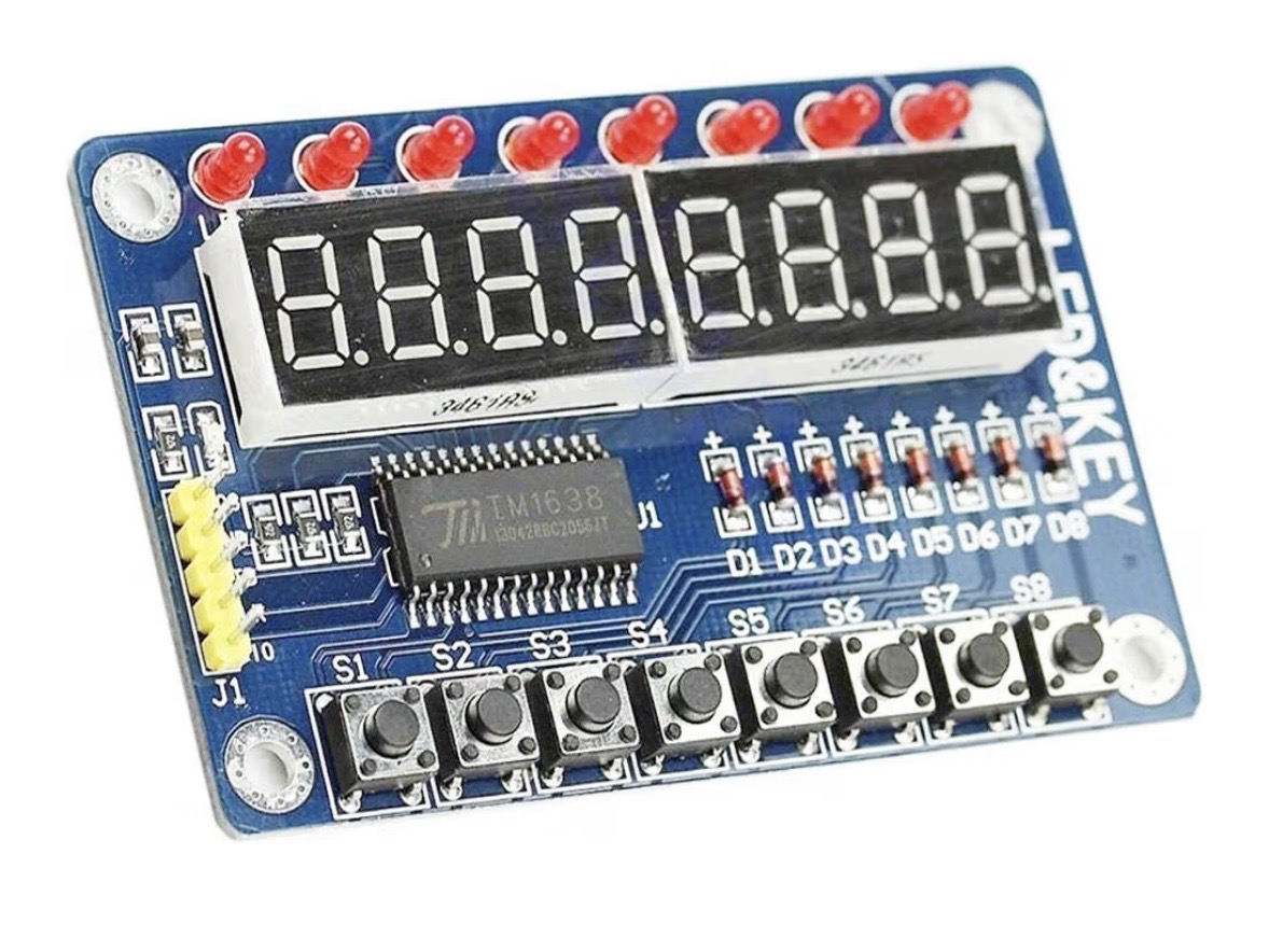
A physical TM1638 pushbutton that controls one of the module's LEDs. Press the key and the LED responds. This is DALE's simplest real-world input → output project.
What You'll Need
- DALE with ESP32-S3
- TM1638 module from Experiment 01
What You'll Learn
- What an input is.
- How a physical pushbutton becomes a Boolean TRUE/FALSE signal.
- How one input can directly control an output.
- How DALE separates what you sense from what you control.
Connect It
Keep the same TM1638 connection from Experiment 01. The module already contains both the pushbuttons and the LEDs we need for this lesson, so there is no new breadboard circuit to build.
Try It in DALE
1. Open the TM1638 Lab
Confirm that the module is connected and responding.
2. Press a key
Press and release one of the TM1638 keys and watch DALE report the change.
3. Test the LED
Turn one of the TM1638 LEDs on and off just as you did in Experiment 01.
What Just Happened?
The pushbutton is an input: it tells the controller something happened. The LED is an output: it lets the controller make something happen. Logic connects those two ideas.
Build It in Logic Builder
Add a TM1638 Key (TM Key) block and select the key you tested. Add a TM1638 LED (TM LED) block and select the LED you tested. Connect the TM1638 Key Boolean output directly to the TM1638 LED input.
Run it. Press the selected TM1638 key → TRUE → LED ON. Release it → FALSE → LED OFF.
BUILD IT VISUALLY. SEE THE REAL CODE.
Show Me The Code
Open Show Me The Code and find the readable variables for the TM1638 Key and TM1638 LED. Follow the generated code from reading the physical key state to updating the LED. You have just turned a visual connection into a real program.